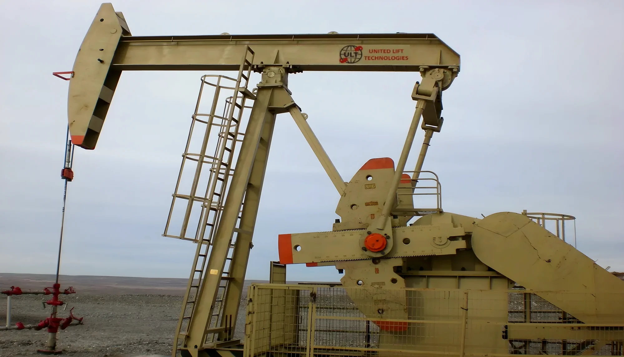
A dynamometer card is a plot of load (vertical axis) against rod position (horizontal axis) over one pump stroke. A surface card is measured at the polished rod with a load cell. A downhole card is calculated from it to show the load on the pump itself. A healthy pump draws a near-rectangle on the downhole card: the plunger picks up the fluid load at the bottom of the stroke, carries it up, and drops it at the top. Changes in that shape point to specific problems.
Surface card and downhole card
The surface card is what a load cell and position sensor actually measure at the polished rod. It includes the weight of the rods, the fluid load, and the stretch, vibration and inertia of a long elastic rod string, so even a perfect pump draws a slanted, wavy shape.
The downhole (pump) card is calculated from the surface card with a wave equation that removes the effects of the rod string. It shows the load at the pump, which is much easier to diagnose. Most modern pump-off controllers calculate it on every stroke.
Read the downhole card for the pump's condition, and the surface card for loads on the rods and the pumping unit.
The shape of a full pump
On a downhole card, a pump that fills completely on every stroke draws an almost rectangular shape:
- Bottom left, start of the upstroke. The travelling valve closes and the plunger picks up the weight of the fluid column. Load rises sharply.
- Top edge, upstroke. The plunger lifts the fluid at a near-constant load.
- Top right, start of the downstroke. The travelling valve opens and the standing valve closes. The fluid load transfers to the tubing and the load drops sharply.
- Bottom edge, downstroke. The plunger moves down through the fluid at a low, near-constant load.
The height of the rectangle is the fluid load on the plunger. Its width is the gross plunger stroke. On a real card, the point on the downstroke where the load drops shows how much of the stroke the plunger travelled through liquid; that effective stroke divided by the gross stroke is the pump fillage.
Common card shapes and what they mean
| Card shape (downhole) | What it means | Usual response |
|---|---|---|
| Full rectangle | The pump fills completely | Nothing; the well may be able to pump faster |
| Load stays high into the downstroke, then drops sharply part way across | Fluid pound: the barrel was only partly full, and the plunger hits fluid on the way down | Slow down or run less often; this is what pump-off control is for |
| Load falls gradually and smoothly on the downstroke | Gas interference: gas in the barrel compresses before the valve opens | Improve gas separation at the intake; consider a gas control pump |
| A thin card with almost no area | Gas lock, or a pumped-off well | Check fluid level; space out the pump; gas control pump |
| Load picks up late at the start of the upstroke and drops off early before the top: both top corners rounded | Leaking travelling valve or plunger slippage | Valve check; pull and repair the pump if it worsens |
| Load unloads slowly at the top of the stroke (rounded top right) and rises before the bottom of the downstroke (rounded bottom left) | Leaking standing valve | Valve check; pull and repair the pump |
| Sharp spike at the bottom or top of the stroke | Pump tagging: the plunger is hitting the bottom or top of the pump | Re-space the pump |
| Loads far below normal, with no fluid load picked up | Parted rods, or a travelling valve stuck open | Stop the unit and investigate |
| Card slanted with long, sloped pick-up and drop-off | Unanchored tubing stretching under load | Anchor the tubing |
These are the classic shapes. A real card often shows more than one at once, so compare it with the well's earlier cards and with production and fluid level data before acting.
Valve checks
A valve check confirms a suspected leak. The unit is stopped part way up the stroke and the load watched: with a good travelling valve the load holds steady, and a falling load means the travelling valve or plunger is leaking. Stopping part way down the stroke checks the standing valve: the load should hold at the buoyant weight of the rods, and a rising load means the standing valve is leaking. Many controllers can run valve checks automatically.
Pump-off control
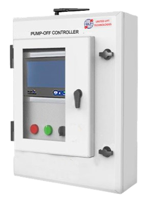
A pump-off controller uses the card to keep the pump matched to what the well can deliver. When fillage drops below a set point, the well is pumping off: the controller either stops the unit for a set idle time so fluid can build up, or, with a variable speed drive, slows the pumping speed. This prevents fluid pound, which damages the pump, rods, tubing and gearbox, and saves power.
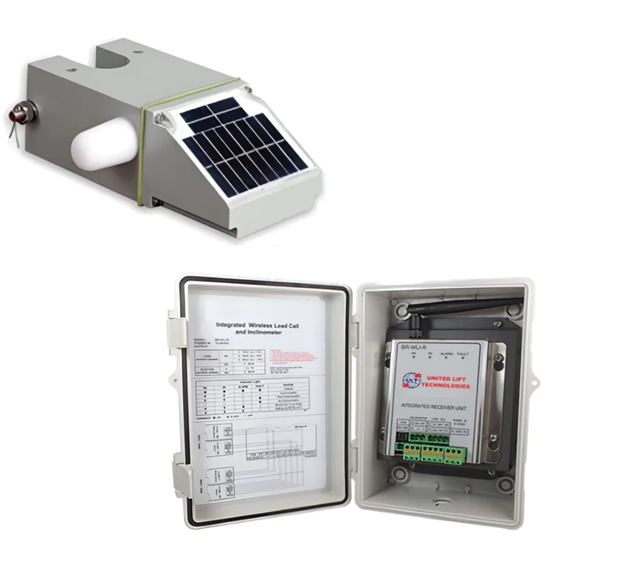
To do this, the controller needs a good card on every stroke. That depends on the load and position sensors at the polished rod. The ULT wireless load cell measures both in one solar-powered unit with no cable to the polished rod, removing a common failure point and cause of lost cards.