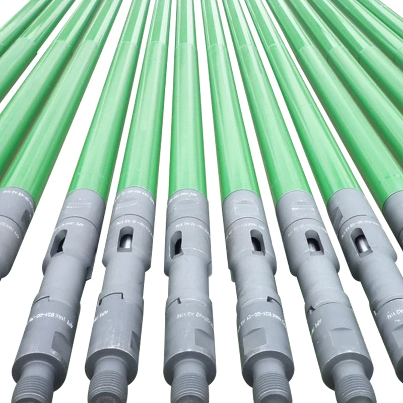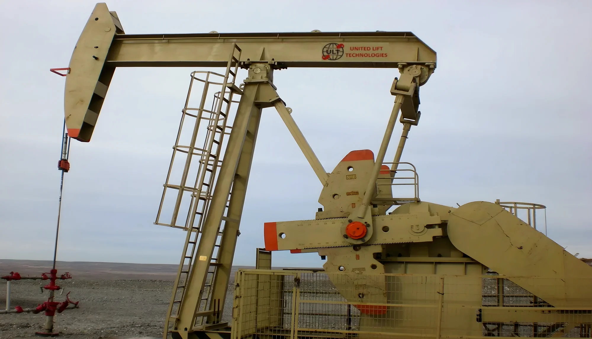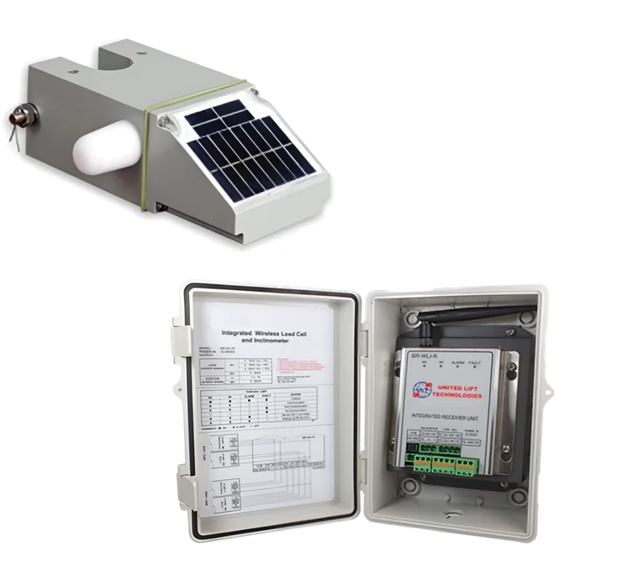
A sucker rod pump is a reciprocating positive displacement pump set near the bottom of the tubing. A pumping unit at surface strokes the rod string up and down. On the upstroke, the travelling valve in the plunger closes and lifts the fluid above it while the standing valve opens to let well fluid into the barrel. On the downstroke, the standing valve closes and the plunger moves down through the fluid with its travelling valve open.
How the pump moves fluid
A sucker rod pump has just two valves, each a ball sitting on a seat. In the usual stationary-barrel pump:
- the standing valve, fixed at the bottom of the pump barrel
- the travelling valve, in the plunger, which moves with the rods
Upstroke. The rods pull the plunger up. The weight of the fluid column above it closes the travelling valve, so the plunger lifts that fluid toward surface. Below the plunger, pressure in the barrel drops, the standing valve opens, and fluid from the well flows in to fill the barrel.
Downstroke. The plunger moves down. Pressure in the barrel rises, which closes the standing valve and opens the travelling valve. The plunger slides down through the fluid now in the barrel, ready to lift it on the next upstroke.
By drawing fluid out of the wellbore, the pump lowers the flowing bottomhole pressure, which lets the reservoir produce. That is why the downhole pump is often called the heart of the sucker rod pumping system. The 3D model above shows both valves through the stroke.
The main parts
| Part | What it does |
|---|---|
| Barrel | Precision-honed tube the plunger runs in; its material and coating are chosen for abrasion and corrosion |
| Plunger | Moves inside the barrel and carries the travelling valve; the gap to the barrel (the plunger fit) controls slippage |
| Travelling valve | Ball and seat in the plunger; closed on the upstroke |
| Standing valve | Ball and seat at the bottom of the barrel; open on the upstroke |
| Valve cages | Guide each ball off and back onto its seat |
| Hold-down | Seals the pump in the seating nipple, with cups or a mechanical lock |
| Seating nipple | The fitting in the tubing that the pump seats into |
Rod pumps and tubing pumps
There are two basic families:
- Rod (insert) pumps are run into the tubing as a complete assembly on the sucker rods and locked into a seating nipple. They can be pulled and replaced without pulling the tubing.
- Tubing pumps have the barrel run as part of the tubing string, and the plunger is run on the rods. This allows a larger bore and more volume from the same tubing size, but the tubing must be pulled to change the barrel.
How to read an API 11AX pump designation
API 11AX sets a standard code that describes a pump's basic configuration (materials and plunger fit are specified separately). Take 25-150-RHBC-16-4-2-2 as an example:
| Part of the code | Example | Meaning |
|---|---|---|
| Tubing size | 25 | 2-7/8 in tubing (15 = 1.900 in, 20 = 2-3/8 in, 25 = 2-7/8 in, 30 = 3-1/2 in) |
| Pump bore | 150 | 1-1/2 in bore (106 = 1-1/16 in, 125 = 1-1/4 in, 150 = 1-1/2 in, 175 = 1-3/4 in, 200 = 2 in, 225 = 2-1/4 in, 275 = 2-3/4 in) |
| Pump type | R | R = rod pump, T = tubing pump |
| Barrel type | H | H = heavy-wall barrel, W = thin-wall barrel, X = heavy-wall barrel with thin-wall threads, S = thin-wall barrel with soft-packed plunger, P = heavy-wall barrel with soft-packed plunger |
| Seat location | B | A = top hold-down, B = bottom hold-down, T = bottom hold-down with travelling barrel |
| Seat type | C | C = cup type, M = mechanical type |
| Barrel length | 16 | 16 ft |
| Plunger length | 4 | 4 ft |
| Upper extension | 2 | 2 ft |
| Lower extension | 2 | 2 ft |
So 25-150-RHBC-16-4-2-2 is a rod pump for 2-7/8 in tubing with a 1-1/2 in bore, heavy-wall barrel, bottom cup-type hold-down, 16 ft barrel, 4 ft plunger and 2 ft extensions at each end. Tubing pumps use a shorter type code such as TH (heavy-wall barrel) or TP (soft-packed plunger).
Top or bottom hold-down? A top hold-down (A) hangs the barrel below the seating nipple, so the standing valve sits lower and sand cannot settle around the barrel. It suits sandy, gassy and low-fluid-level wells, but its depth is limited because the barrel carries the full fluid pressure. A bottom hold-down (B) is surrounded by tubing pressure, so it suits deep wells; its drawback is that sand can settle between the barrel and the tubing. A travelling barrel (T) keeps sand moving and from settling into the pump when it stops, so it suits sandy and intermittently pumped wells, but it is a poor choice for gassy or low-fluid-level wells.
How much will a pump produce?
The theoretical output of a sucker rod pump is:
Displacement (bbl/day) = 0.1166 × plunger diameter² (in) × net plunger stroke (in) × strokes per minute
For example, a 1-1/2 in pump with a 100 in net stroke at 8 strokes per minute displaces about 0.1166 × 2.25 × 100 × 8 = 210 bbl/day.
Actual production is lower. Rod and tubing stretch make the downhole plunger stroke shorter than the surface stroke, some fluid slips past the plunger, and gas takes up space in the barrel. Volumetric efficiency of 70 to 90% is a reasonable expectation in a well-designed system without much gas. A dynamometer card shows what the pump is actually doing.
Choosing materials
Barrel and plunger materials are picked for the well's mix of abrasion and corrosion:
- Carbonitrided steel barrels for moderate to severe abrasion with mild to moderate corrosion, and a 5% chrome version for more corrosion resistance
- Brass barrels for corrosive wells without much abrasion
- Chrome-plated or nickel carbide-plated barrels for harder wearing or more corrosion-resistant surfaces
- Spray metal plungers for general service, chrome-plated plungers for hardness, and Monel pin plungers for severe corrosion and abrasion
- Valve balls and seats in stainless steel, Stellite, tungsten carbide, titanium carbide or nickel carbide, depending on wear and corrosion
The ULT downhole pumps page lists the materials, coatings and hardness of each option.
Common pump problems
| Problem | What happens | Usual fix |
|---|---|---|
| Gas interference | Gas fills part of the barrel, so the plunger compresses gas instead of lifting liquid | Better gas separation at the intake, a gas control pump, slower pumping |
| Gas lock | The barrel fills with gas and the valves stop opening | Gas control pump with a forced-open travelling valve, lower pump intake |
| Fluid pound | The pump strokes faster than the well can fill it, so the plunger hits the fluid on the downstroke | Pump-off control or a variable speed drive |
| Sand wear | Solids cut the plunger, barrel, balls and seats | Sand control pump, top hold-down, harder materials |
| Leaking valves | Worn or corroded ball and seat let fluid slip back | Replace balls and seats; choose harder or more corrosion-resistant materials |