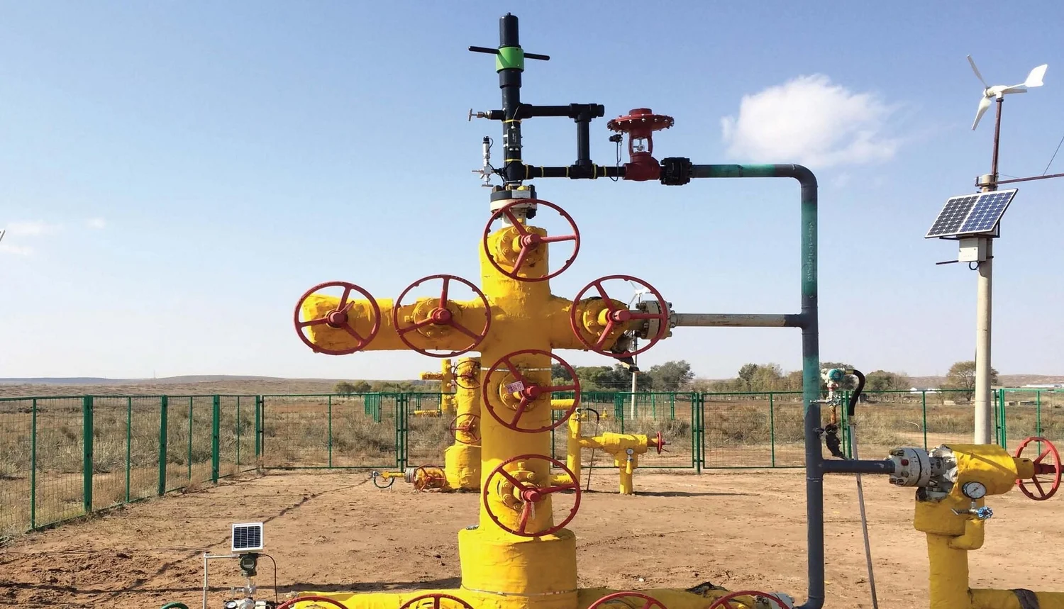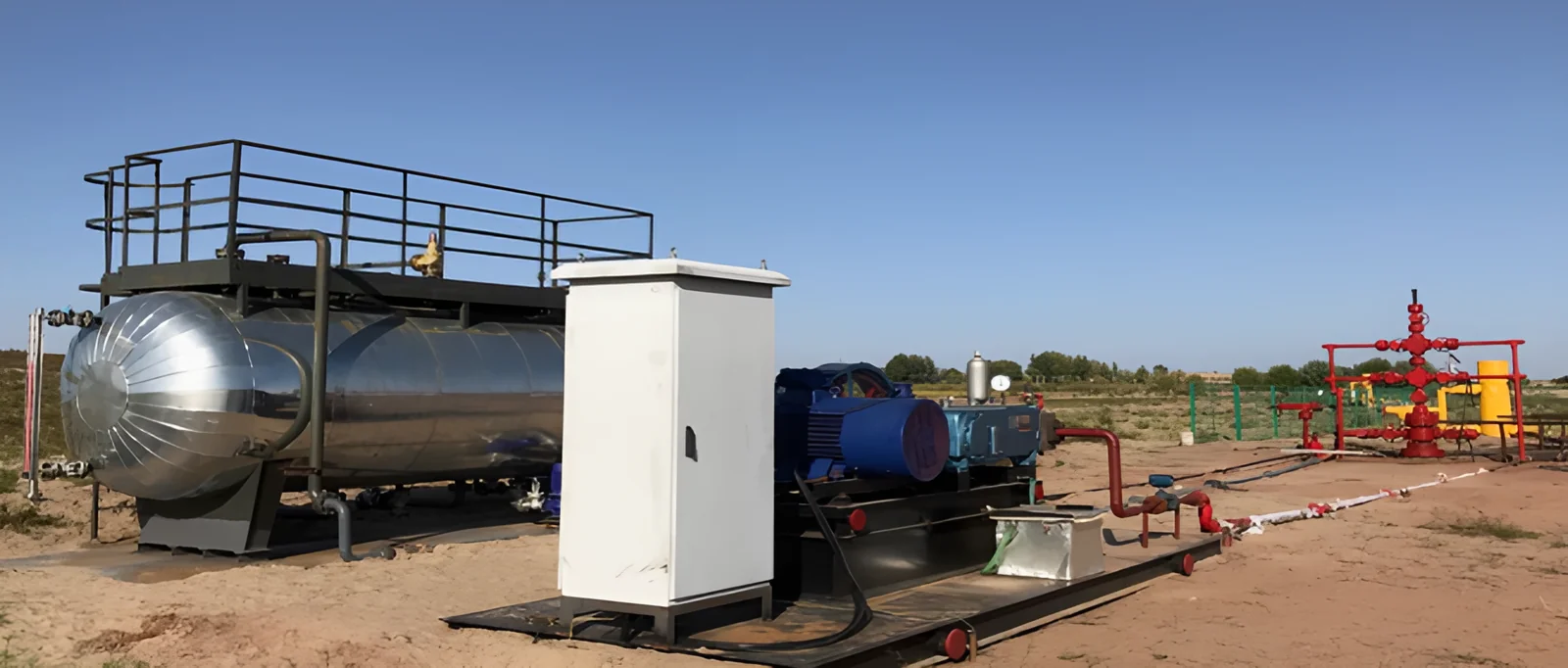
Plunger lift removes liquid from a gas or high gas-liquid ratio oil well using the well's own energy. A motor valve shuts the well in so pressure builds while a plunger falls to the bottom of the tubing. When the valve opens, the stored gas pushes the plunger and the liquid above it to surface. The plunger acts as a seal between gas and liquid, so very little gas slips past and very little liquid falls back.
Why wells need plunger lift
A gas well carries liquid (water, condensate or oil) to surface only while the gas moves fast enough. As reservoir pressure declines, gas velocity drops below that point and liquid starts to collect in the tubing. The liquid column pushes back on the formation, the gas rate falls further, and the well "loads up" until it produces erratically or dies.
Plunger lift breaks that cycle. Instead of relying on gas velocity to lift liquid as droplets, it lifts the liquid as a slug on top of a solid interface. The only energy it uses is the gas the well already has, so there is no pump to power and no rods to run.
The plunger lift cycle, step by step
The 3D model above runs the same cycle on a loop, and its labels show which stage the plunger is in.
- Fall (shut-in). The controller closes the motor valve. Flow stops, and the plunger drops through the gas and then the liquid in the tubing until it lands on the bumper spring at the bottom.
- Build-up. With the well shut in, gas from the formation builds pressure in the casing annulus. The controller waits until there is enough stored energy to lift the plunger and the liquid slug above it.
- Unloading. The motor valve opens. Tubing pressure drops to line pressure, the gas in the annulus expands into the tubing below the plunger, and it drives the plunger and its liquid slug up the tubing.
- Arrival. The plunger reaches the lubricator at the wellhead. The liquid goes down the flowline, and the arrival sensor tells the controller exactly when the plunger arrived.
- Afterflow. The well keeps flowing gas with the plunger held at surface by the gas flow or by the catcher. When the flow rate falls to the point where liquid would start loading again, the controller closes the valve and the plunger falls for the next cycle.
The cycle repeats many times a day. Getting the timing right, long enough shut-in to lift the plunger reliably and long enough afterflow to sell as much gas as possible, is most of the work of running a plunger lift well.
Surface and downhole equipment
| Component | Where it sits | What it does |
|---|---|---|
| Plunger | Inside the tubing | Free-travelling piston that seals between the gas below and the liquid above |
| Bumper spring and hold-down | Bottom of the tubing | Stops the falling plunger and absorbs its impact; set in a seating nipple, or with a tubing stop or collar stop where there is none |
| Lubricator | Top of the wellhead | Receives the plunger at surface, with a shock spring to absorb the arrival, flow ports to the flowline and a catcher to hold the plunger |
| Arrival sensor | On the lubricator | Detects the plunger's arrival so the controller can time the cycle |
| Motor valve | In the flowline | Opens and closes the well on the controller's signal |
| Pressure sensors | Casing, tubing and flowline | Measure the pressures the controller uses to decide when to open and close |
| Controller | At the wellhead | Runs the cycle from timers, pressures and arrival data, and logs every cycle |
ULT supplies all of these. See the plunger lift system for sizes and ratings: plungers, hold-downs and lubricators come in 2-3/8, 2-7/8, 3-1/2 and 4 in.
Which plunger to use
| Plunger | Best for |
|---|---|
| Solid (spiral) | Wells with low to moderate gas volumes; simple, efficient liquid removal |
| Padded | A tighter seal against the tubing wall, so less liquid falls back past the plunger |
| Continuous flow (bypass) | High-velocity gas wells that need very short shut-in times; it falls against flow with its bypass open |
| Brush | Wells producing solids such as sand, salt or coal fines |
| Intelligent | Sensor-equipped plungers that log temperature, pressure and acceleration on every trip |
How the controller sets the cycle
The simplest controllers open and close on fixed timers. Better control uses what the well is telling you:
- Pressures. Casing pressure shows how much energy has built up during shut-in. The difference between casing and tubing pressure gives a rough idea of how much liquid is sitting in the tubing.
- Arrival time. How long the plunger takes to reach surface is the best single measure of whether the cycle is right. A plunger that arrives very fast had more energy than it needed, which wastes shut-in time and can damage the lubricator. A plunger that arrives slowly, or not at all, did not have enough.
- Downhole data. An intelligent plunger records conditions on every trip and hands its data over at each arrival. The controller can use it to estimate the liquid column and set the next open and shut-in times.
A good starting point is the shortest shut-in that still gives reliable arrivals, then as much afterflow as the well can carry without loading up. Controllers that adjust these times automatically from arrival speed and pressures take most of the tuning off the operator. If a plunger fails to arrive, the controller should hold the well shut in longer so it can recover before the next attempt.
Which wells suit plunger lift
Plunger lift is usually the lowest-cost form of artificial lift, and it works best on:
- gas wells that are starting to load up with liquid
- oil wells with a high gas-liquid ratio (GLR)
- wells with paraffin or scale, since the plunger wipes the tubing wall on every trip
- remote wells, because the controller runs on a small solar panel and battery
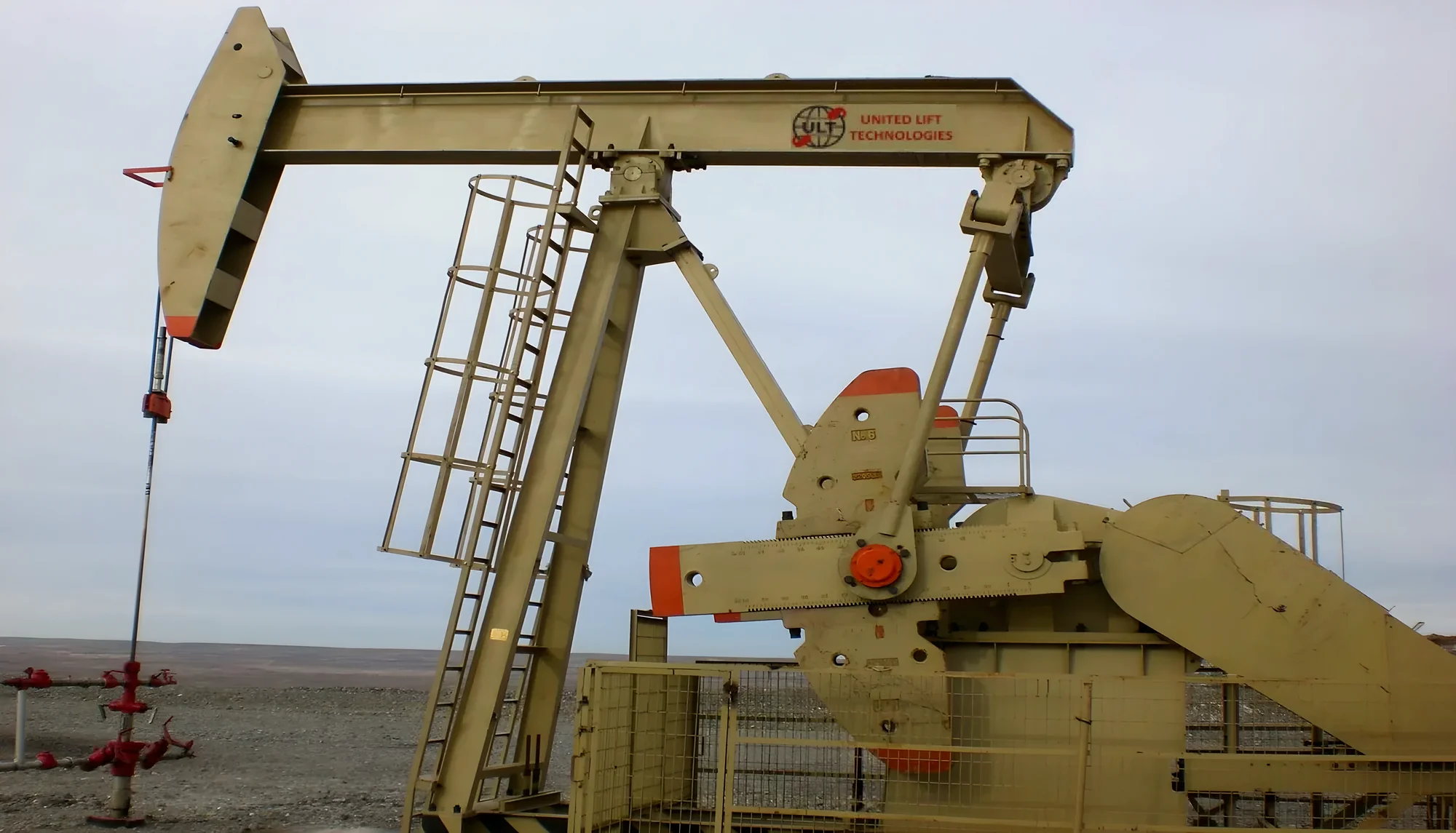
It needs enough gas to lift the liquid. A commonly used rule of thumb is a gas-liquid ratio of at least about 400 scf per barrel for every 1,000 ft of well depth, though casing pressure, line pressure and liquid rate all matter. Wells that produce more liquid than the gas can carry, or very little gas, are better suited to a pump: compare the jet pump for sandy, deviated or high-rate wells and a beam pumping unit with a downhole rod pump for liquid-rich oil wells.
Common problems and what they mean
| Symptom | Likely cause | What to check |
|---|---|---|
| Plunger does not arrive | Not enough pressure built up, too much liquid, or a worn plunger letting gas slip past | Lengthen shut-in, check casing pressure, inspect the plunger for wear |
| Very fast arrivals | Too much stored energy or too little liquid above the plunger | Shorten shut-in and check the lubricator shock spring. Fast or dry arrivals can damage the lubricator and are a safety hazard: never let the plunger run without liquid above it |
| Gas rate falls cycle after cycle | Afterflow too long, so the well loads up before shutting in | Shorten afterflow, or close on flow rate rather than a timer |
| Plunger wears quickly | Sand or solids, or arrivals too fast | Consider a brush plunger and slow the arrivals |